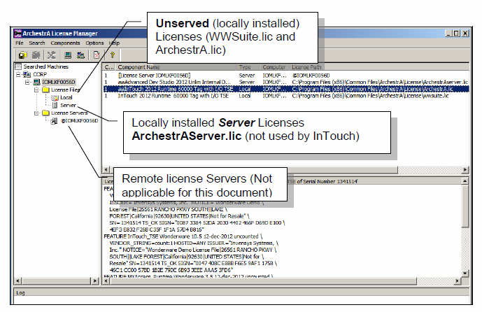
It is composed of a browser-based License Manager and a License Server that work together to allow you to share and deliver licenses for your installed products with or without an Internet connection. License Manager and License Server are installed as part of the product installation process. Activate your AVEVA Edge License. Select the type of license you want to activate and follow the instructions: Install or Upgrade a Softkey license on the PC – Development (IDE) and/or Full Runtime. Close AVEVA Edge (make sure that the process “Studio Manager.exe” is not running) Run the “Register” module (Windows button “Register. Manage your risk capital as you build market share for your software products and cloud services, using our monthly subscription based software license management services. Our solutions mostly run in internal security zones so we have to support activation of licenses on systems that have no external network connections.
A very powerful and useful feature added in later versions of Archestra is the layering wizard. The layering wizard feature allows you to make versatile graphic symbols fitting multiple scenarios.
Some ways I have seen wizards used is to represent several types of motors in a single symbol, or analog displays with options to change display format when the symbol is dropped on a screen or into another symbol.
The layers can be combined to create some very complex configurations although I would caution you to keep it as simple as possible. I have also witnessed first hand the pain of trying to modify or make updates to these rather complex creations only to find myself playing the “mole game” making a change in one thing only to discover it broke something in the layering that was seemingly unrelated. Keep it simple.
For this tutorial I have chosen a simple dual orientation valve graphic, it’s a commonly used symbol and perfect for wizard layering. In the older versions of Archestra if you wanted a valve symbol to indicate both in a vertical and a horizontal position you had two choices, either place visibility on the elements activated by some external, or build two separate symbols.
Layering solves this problem by giving your symbol intelligent configuration available at design time.

Step 1 to create a simple dual orientation valve symbol is to create your symbol with the necessary elements and properties. In this example I chose to make a valve that would display green if on or dark gray if off.
A public Boolean custom property is added to the valve symbol and default object reference provided that will coincide later with an object attribute. Note: Using a custom property allows you to choose an attribute other than “me.valve” later when the graphic is dropped into a screen or symbol.
Each valve is represented by two groups of triangle polygons grouped by orientation, vertical or horizontal, then centered on each other.
Each polygon is animated in exactly the same way using the “Value” custom property to manipulate the Fill Style between either green or dark gray.
Step 2 after completing the element animation configuration, is to establish and configure wizard layers.
In the Options pane of the Valve graphic editor select the new folders icon and create an option folder named “orientation”. This will become a configurable property available in the symbol property window at design time.
Now, select the Orientation folder you just created clicking the Add Choice icon making two choices one named “Horizontal” the other named “Vertical” this will appear in the Orientation property as drop down items at design time.Now when switching to the Layers menu you will find that a layer has been created for each of the choices associated with your Orientation choice group.

Each layer has a folder for associated Custom Properties, Graphic Elements, and Named Scripts.
In this example we will need to associate our two symbol groups with appropriate layer folder, since we are not using any scripts that folder is left empty and since our custom property is global to both layers it will associate with both by default. (Note: Once a script, element, or property has been associated with a layer it will only be available to the layer its associated with.)
To associate the two valve element groups all we need to do is drag and drop the group from the Elements pane to the Layers pane.
Now that the two groups are associated properly the valve symbol is complete.
One other thing I wanted to mention is that the small “eyeball” icon is used to make the layer visible or not while you are working in the symbol. If I want to know how the graphic will appear for each choice I only need to click the eyeball next to the group and toggle its visibility state. The eyeball on the Layer bar toggles visibility for all layers .This feature is only used at design time with no effect on the symbol at runtime.
When in use the valve graphic orientation is selected from the choice group drop down.
Archestra License Manager
I hope this tutorial has helped you, please leave a comment. If you would like to learn more about this tutorial you can find the video version of it on my YouTube channel here.
My Free Online training course is here.
I am getting ready to launch the book Step By Step Archestra Scripting in October, I am offering a couple of one time bonuses to anyone pre-ordering the book. If you pre-order now you will get access to the companion online course at no additional charge and one year access to the online support forum I am launching at the same time.
You can pre-order the book Step By Step Archestra Scripting here.
Step-by-Step Archestra Scripting Guide
Archestra License Manager Job
Subscribe now to receive FREE Tutorials and Scripting Examples
Archestra License Manager Missing
We will never share or sell your email address.